
Global high-mix volume high-speed PCBA manufacturer
9:00 -18:00, Mon. - Fri. (GMT+8)
9:00 -12:00, Sat. (GMT+8)
(Except Chinese public holidays)





HomePage > Blog > Knowledge Base > Humanoid Robot PCB Assembly: From Joint Drivers to AI Computing Boards
1. From Joint Drivers to AI Computing Boards: What Needs to Be Assembled?
2. What Must Be Reviewed Before Assembly?
3. Assembly Challenges in Joint Drivers and AI Computing Boards
4. Testing Each Board for Its Intended Function
5. Keeping Multiple Board Assemblies Consistent in Production
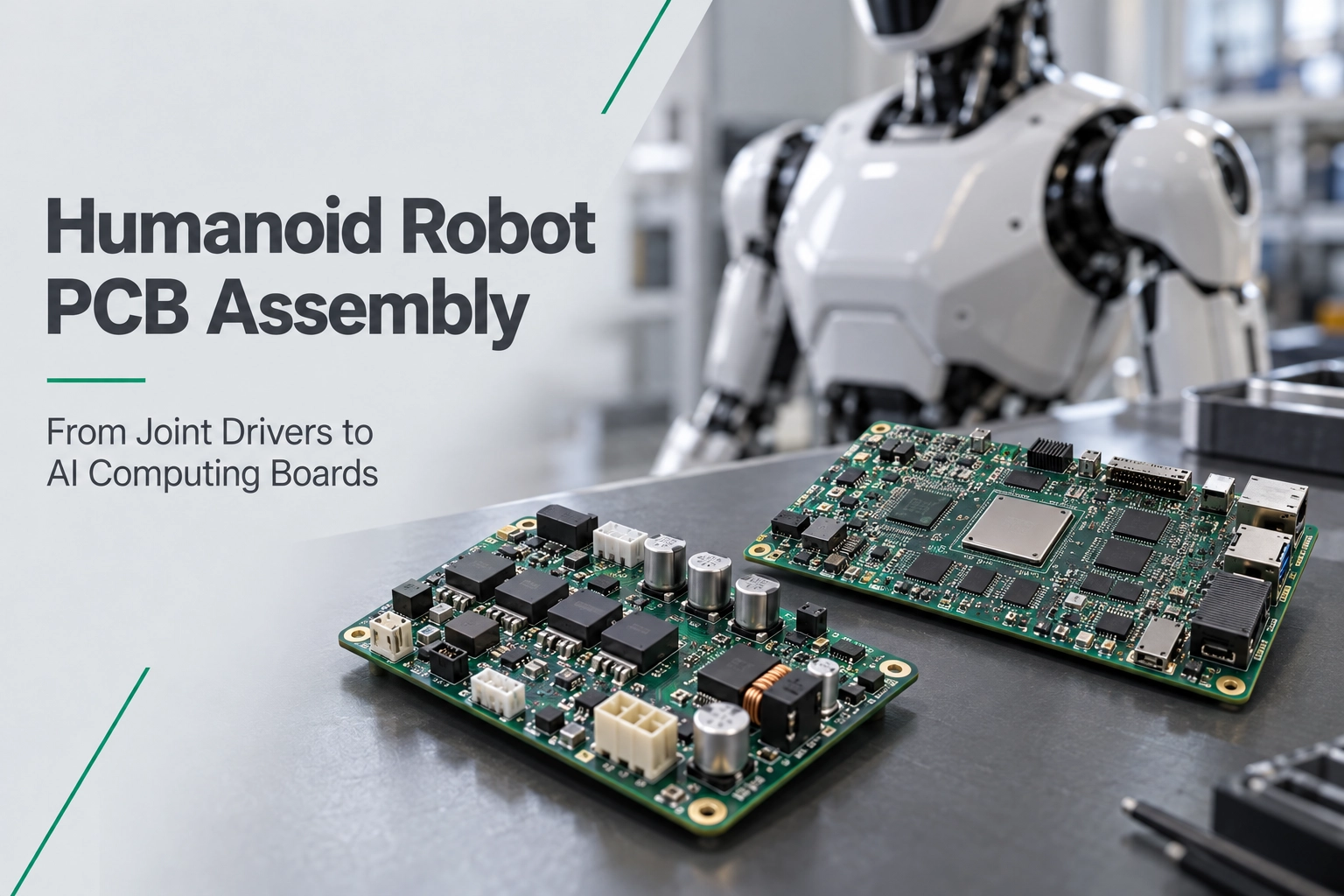
Humanoid robot PCB assembly includes several circuit boards that operate together inside a small and continuously moving framework. The joint driver is in charge of controlling and feedbacking the power switch. The AI computing board works with data via densely packed components and connections. Each type of board needs a specific assembling process and testing strategy.
But for engineers and those in procurement, the biggest problem is to make these various parts with the same high quality each time. In this article, we will explore the humanoid robotics PCB assembly, beginning with the choice of boards and reviewing the files, and then moving on to welding, testing, and managing the production process.
What types of circuit boards are used in humanoid robots? Besides AI computing board, you can also find joint drive boards, sensor interface boards, and communication and power supply boards in it. They can be set on their own or combined with certain features. For humanoid robot PCB assembly, we need to first understand what each board can do.
|
Board type |
Primary function |
Assembly and testing focus |
|
Joint drive board |
Motor control |
Power soldering and load testing |
|
AI computing / main control board |
Processing and control |
Fine pitch assembly and interface verification |
|
Camera / sensor interface board |
Vision and sensing |
Connections and signal checks |
|
Communication board |
Data transfer |
Interface testing |
|
Power / BMS / charging board |
Power and battery management |
Power connections and protection checks |
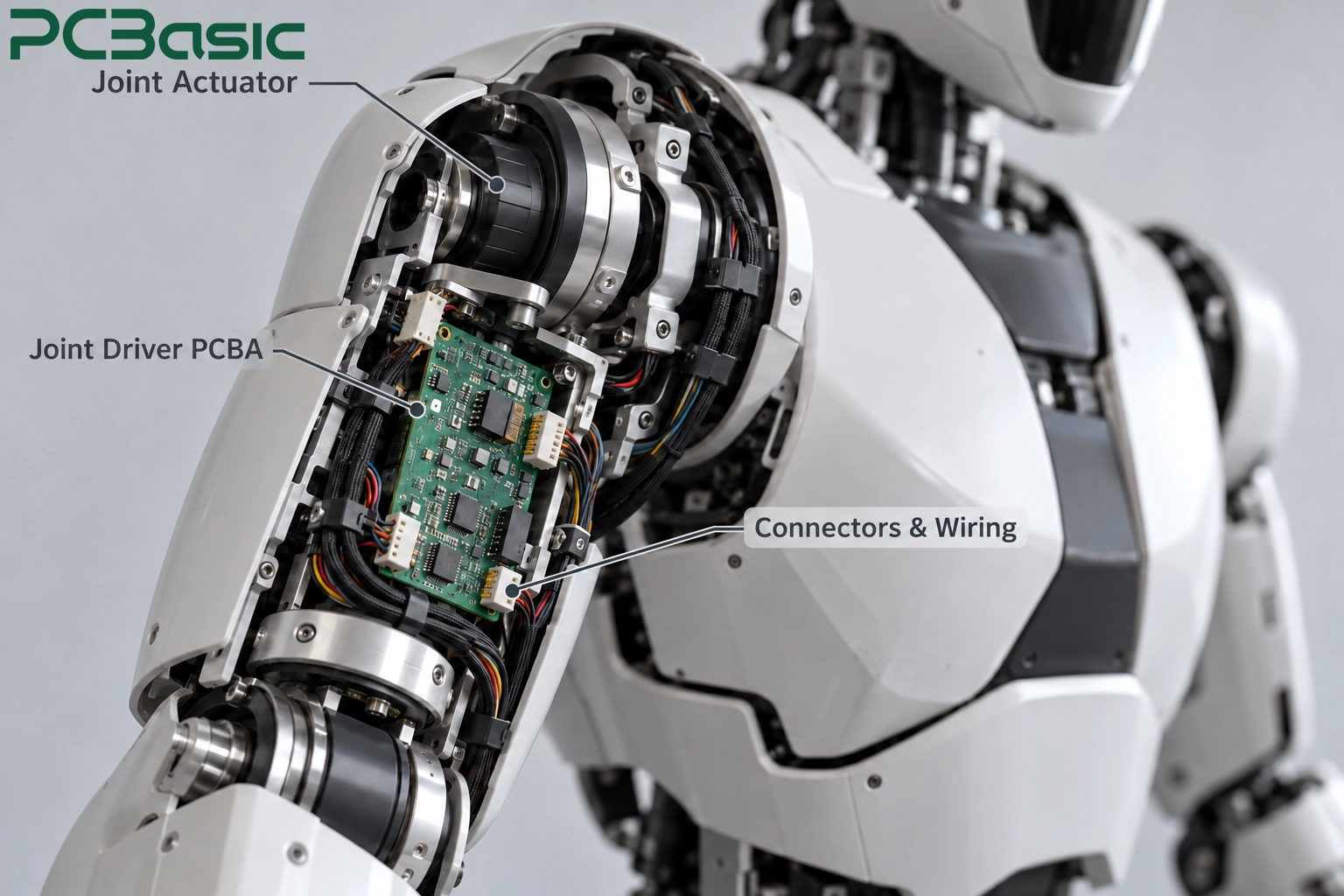
MOSFETs, gate drivers, current sensing circuits, and controllers are common components of robot joint driver PCBs. Some are housed within the actuator, while others are linked to the motor via wires. Different mounting techniques result in varying accessible cooling space and connection placements. Before we start to assemble, we must first check these.
This kind of humanoid robot PCBA usually includes a processor, memory, and several fast interfaces. AI computing and real-time motion control can be managed by the same board or by different boards. When we test something, we have to look at the real setup and can't just say the whole board is working fine just because it started up successfully.
The place where the auxiliary boards are attached also needs to be considered. Boards near the motor might get hot or shake, and boards inside the hand could have issues like not enough room and wires moving when the joints bend. Each humanoid robot circuit board needs to be chosen with the right type of structure—rigid, flexible, or rigid-flex—depending on how it will actually be installed.
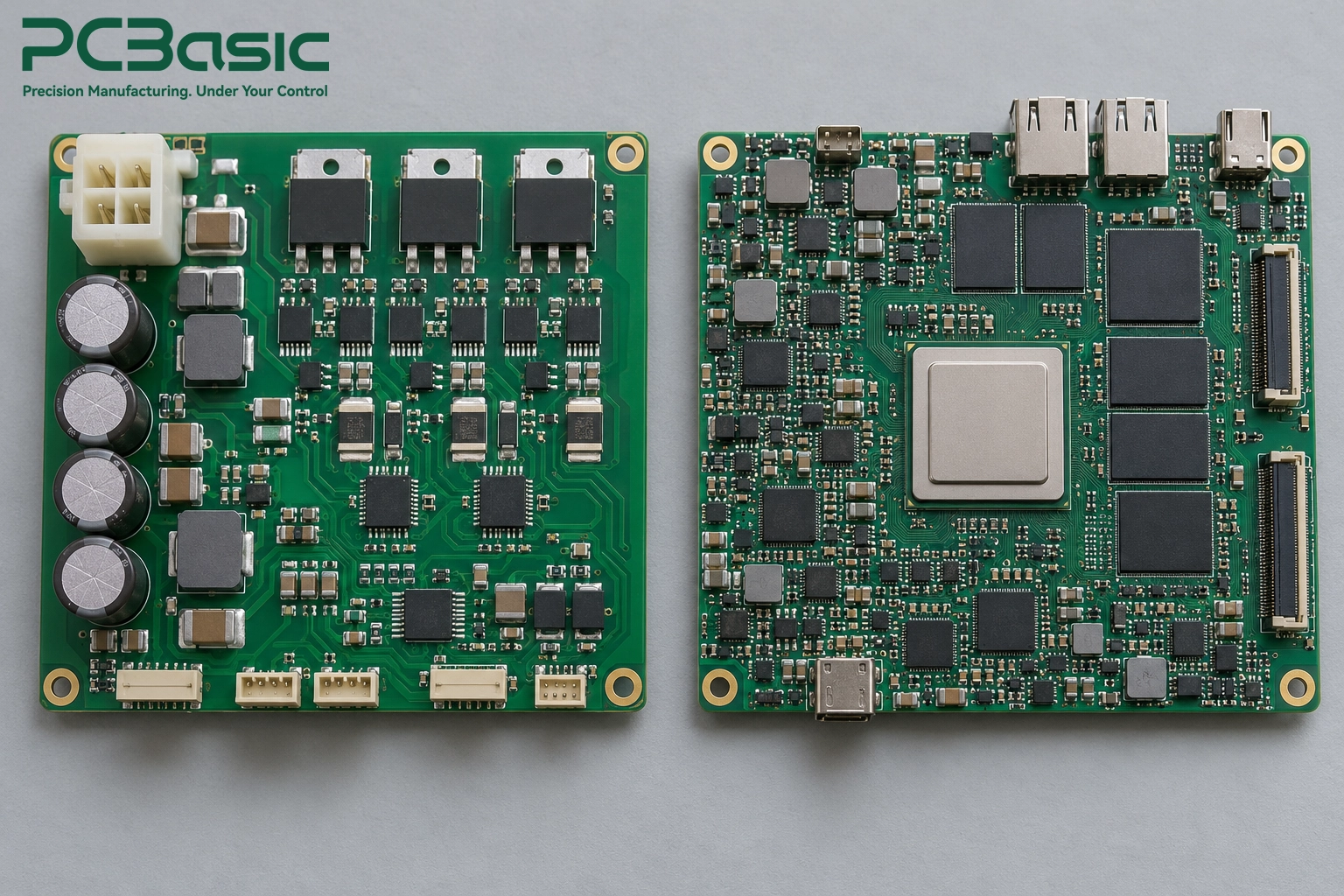
Before starting humanoid robot PCB assembly, the design in your hands may have been revised several times. The board file is the latest version, but the BOM and component placement coordinates may not have been updated synchronously. Before sending these materials to the manufacturer, review and compare all of them together, especially for the recently modified components and positions.
Also, there are alternative materials. Even if the parameters are similar, we still need to verify the packaging, thermal requirements and firmware compatibility. The approved alternative models should be marked in the BOM, and moisture-sensitive components, fine-pitch devices and special connectors can also be noted together to facilitate the manufacturer's preparation.
Just because a humanoid robot PCB can fit into the enclosure doesn't mean that the connectors, heat sinks, and test interfaces are all easy to operate. The installation diagram can supplement the space limitations that are not visible in the Gerber files.
In humanoid robot PCB manufacturing, the stack-up, copper distribution and surface treatment need to be coordinated with the subsequent assembly. The flexible areas should be explained whether they are bent during installation or undergo repeated movements with the joints. For multi-panel projects, the corresponding hardware and firmware versions also need to be confirmed.
When discussing humanoid robot PCB assembly services with PCBasic, you can send the installation diagram, mechanical restrictions and test requirements along with the BOM. You don't need to write a long explanation. The main thing is to make clear the requirements that aren't shown in the files. This way, the quotes and production plans can be made with accurate information.

The assembly requirements for the joint drive board and the AI computing board are different. For the former, attention needs to be paid to the welding of power devices and the connection for heat dissipation. For the latter, the key challenge lies in the dense placement of components and the fact that some solder joints are hidden beneath the package. The internal space of the robot is limited, and during operation, there are movements and vibrations, so the fixation of connectors and the support of the board cards also need to be considered.
When assembling the robot joint driver PCB, we need to pay attention to the temperature differences in various areas and whether the thermal pads are properly soldered.
• Reflow soldering temperature curve: Large connectors may heat up more slowly, and the temperature limits of nearby small devices should also be taken into account.
• Thermal pad soldering: The connection quality under the package, related to the opening of the steel mesh and the amount of solder paste.
• Joint acceptance: To what extent can voids be allowed? It should be confirmed in advance according to the specific package.
• Heat sink installation: Leave enough surrounding space to facilitate the installation operation.
For boards with dense components, humanoid robot PCB assembly requires controlling the process from solder paste printing.
• Solder paste printing: Before mounting, check the amount and position of the solder paste through SPI.
• Component handling: The storage conditions and exposure time of sensitive components should be controlled as required.
• Board support: Thin boards or special-shaped boards may require supporting fixtures.
• Hidden connections: The bottom solder joints of BGA are not visible, so appropriate X-ray inspection and electrical checks are needed.
When the robot moves, the cables may pull the connectors, and vibration can also affect higher or heavier components. When assembling the circuit board of a humanoid robot, we need to combine mechanical design to determine the soldering and fixation methods of the connectors, as well as which components need local reinforcement.
Flexible areas may require carrier support. If coating or gluing is to be used for reinforcement, it is also necessary to specify which areas need to be covered and which need to be shielded to avoid affecting the connector insertion, test point contact or heat sink installation.
PCBasic can handle SMT, through-hole, and mixed technology assembly, and it can offer conformal coating as needed. When conducting humanoid robot PCB assembly, we will combine the board card structure and usage conditions to confirm the welding sequence, fixtures, and protection measures.
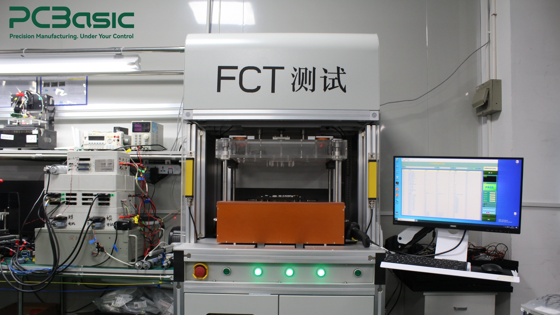
After the board is powered on, what else needs to be checked? During humanoid robot PCB testing, we not only need to check the assembly quality but also confirm that each board can perform the corresponding functions.
• SPI/AOI: Check the solder paste printing, component mounting, and visible assembly defects separately.
• X-ray: Inspect the solder joints of BGA and other bottom-mounted connection packages that are hidden below.
• ICT/Flying probe: According to the contact condition of the test points, check specific electrical faults.
These checks need to be coordinated with the PCBA functional testing. Leave the test points and programming interfaces in advance, and the subsequent tests will be more convenient.
When testing the robot joint driver PCB, we need to check current detection, position feedback, communication, and the specified protection functions. Some checks require connecting the motor or load fixture to observe the load performance. Voltage, load, test duration, and temperature limits should be determined in advance.
For AI computing-based humanoid robot PCBA, we need to check startup, power rails, memory, and interfaces. Next, we will confirm through integration testing whether the computing board, sensor board, and drive board can work together. Vibration, temperature cycling or aging tests will be arranged according to project requirements separately.
PCBasic supports inspection, electrical testing, and FCT. When consulting humanoid robot PCB assembly services, you can provide test procedures and acceptance limits to facilitate us in confirming what needs to be checked for each board.
Humanoid robots usually have multiple boards. When the number increases, subsequent batches need to be produced according to the confirmed version and ensure that all boards can be used in conjunction.
For humanoid robot PCB assembly, after the first piece is confirmed, the board version, BOM, firmware and test programs should be recorded as the basis for subsequent production. The requirements for coating, reinforcement and heat-conducting materials should also be clearly stated.
Before replacing components or updating firmware, assess the impact and confirm the matching version. This can reduce the situation where a single board passes testing normally but problems occur when put together.
Approved substitutes should be clearly marked. The bare board specifications for humanoid robot PCB manufacturing also need to be managed in accordance with the version.
Each humanoid robot PCBA should be associated with materials, assembly and test records to facilitate the investigation of affected batches when faults occur. PCBasic records production information through MES. Before you return the order, you can specify the required records and change approval requirements to facilitate subsequent batches to be produced according to the confirmed configuration.

The AI board can operate normally, but the robot still requires other board for coordination. The joint drive board needs load performance and feedback, while the sensing, communication and power supply boards also have their own functions that need to be verified. In humanoid robot PCB assembly, we need to implement these requirements in the production and testing processes, and have subsequent batches follow the confirmed documents and versions.
If you are preparing a project, you can contact PCBasic and provide Gerber files, BOM, quantity and test requirements. If there are any limitations in installation space or connector positions, please also explain them to facilitate the engineering team in evaluating the required assembly processes and test arrangements.
Q1: Do humanoid robots need flex or rigid-flex PCBs?
Not always. A humanoid robot PCB can use rigid, flex, or rigid-flex construction, depending on installation space and movement requirements.
Q2: What tests are needed for humanoid robot boards?
Humanoid robot PCB testing includes inspection, electrical checks, and functional tests. Joint drivers may also need load checks, while AI boards need memory and interface verification.
Q3: What files are needed for an assembly quote?
For humanoid robot PCB assembly services, send Gerber files, BOM, placement data, assembly drawings, and quantities, along with any programming, testing, or mechanical requirements.
Assembly Enquiry
Instant Quote

Phone contact

+86-755-27218592
In addition, we've prepared a Help Center. We recommend checking it before reaching out, as your question and its answer may already be clearly explained there.
Wechat Support

In addition, we've prepared a Help Center. We recommend checking it before reaching out, as your question and its answer may already be clearly explained there.
WhatsApp Support

In addition, we've prepared a Help Center. We recommend checking it before reaching out, as your question and its answer may already be clearly explained there.
