Table
of Contents
1. Check Power and Antenna Connections Before
Testing
2. Reading GPS Test Results: Serial Output,
Satellite Tracking, and a Valid Fix
3. Troubleshooting Sequence: Why a GPS
Receiver Responds but Cannot Get a Fix
4. Production Testing: Signal Conditions and
Pass/Fail Criteria
5. Conclusion
6. FAQs
You’ve just pulled the first batch of a new
hardware design off the SMT line. The components are placed cleanly, and the
solder joints under inspection look solid. Yet, the real engineering
verification begins right now: validating the GPS receiver PCB assembly.
Getting a GPS receiver board to successfully
boot is only half the battle. The true test of a robust GPS receiver PCBA lies
in its ability to lock onto orbital satellites, maintain signal integrity in
noisy electromagnetic environments, and deliver a reliable position fix.
Whether you are building a compact asset tracker or a complex GPS navigation PCB
assembly, verifying post-soldering performance requires a methodical approach
that bridges RF engineering with practical production line testing.
This guide breaks down how to systematically
verify a newly assembled GPS receiver PCB, troubleshoot common post-reflow
pitfalls, and establish reliable pass/fail criteria that align with your test
engineering standards.
Check Power and Antenna Connections Before Testing
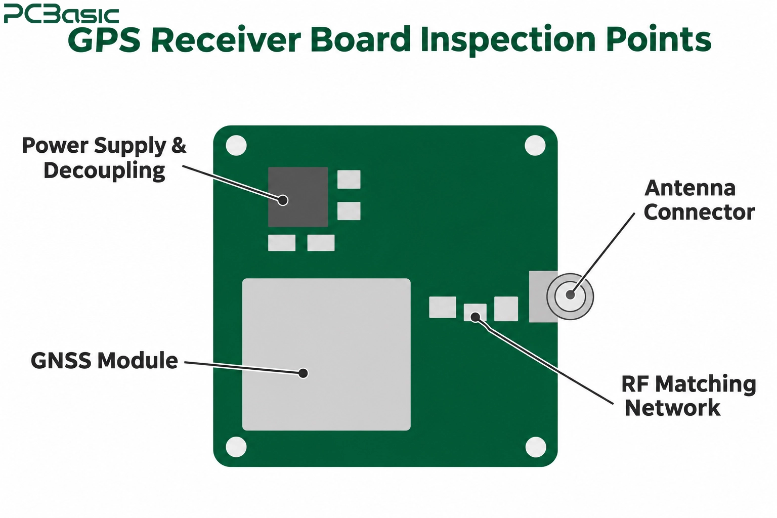
Before you connect your GPS receiver board to a
logic analyzer or send serial configuration commands, inspect the physical
layer. RF circuits are sensitive to layout deviations and assembly defects.
1.
Power Supply Integrity
Most GNSS modules rely on specific voltage
rails (commonly 3.0V to 3.3V, as specified in the manufacturer's datasheet),
which may be fed by low dropout regulators (LDOs). During your initial
inspection of the GPS receiver PCBA, check the decoupling capacitors closest to
the module’s VCC pins—such as recommended 0.1µF bypass capacitors where
recommended. A cold-soldered or misplaced capacitor can reduce supply-noise
suppression, allowing noise to affect the receiver's front-end and potentially
raising the noise floor. Use an oscilloscope to measure voltage ripple under
load against your module’s recommended limits.
2.
The Critical GPS Antenna Connection
The path between the antenna pad and the GNSS
chip is where assembly errors frequently occur. Whether your design uses an
active patch antenna, an onboard ceramic chip antenna, or an external U.FL
connector, the GPS antenna connection requires precise execution:
• Impedance Matching: Verify that your 50-ohm microstrip or coplanar waveguide
transmission line has no width discontinuities, solder bridging, or missing
matching components (inductors and capacitors).
• Bias-Tee (Active Antennas
Only): If your design uses an active antenna
with an external bias tee, verify that the DC blocking capacitor and the
inductor supplying DC bias voltage to the center conductor are correctly
populated. Omitting this inductor can cut power to the active antenna's
internal LNA, resulting in severely degraded reception. Passive antennas do not
require this bias circuitry.
• Ground Clearances: Check that the antenna keep-out areas and RF feed reference ground
match your approved PCB layout. Stray copper pouring too close to the antenna
or matching components can detune the antenna or matching network.
Reading GPS Test Results: Serial Output, Satellite Tracking, and a Valid
Fix
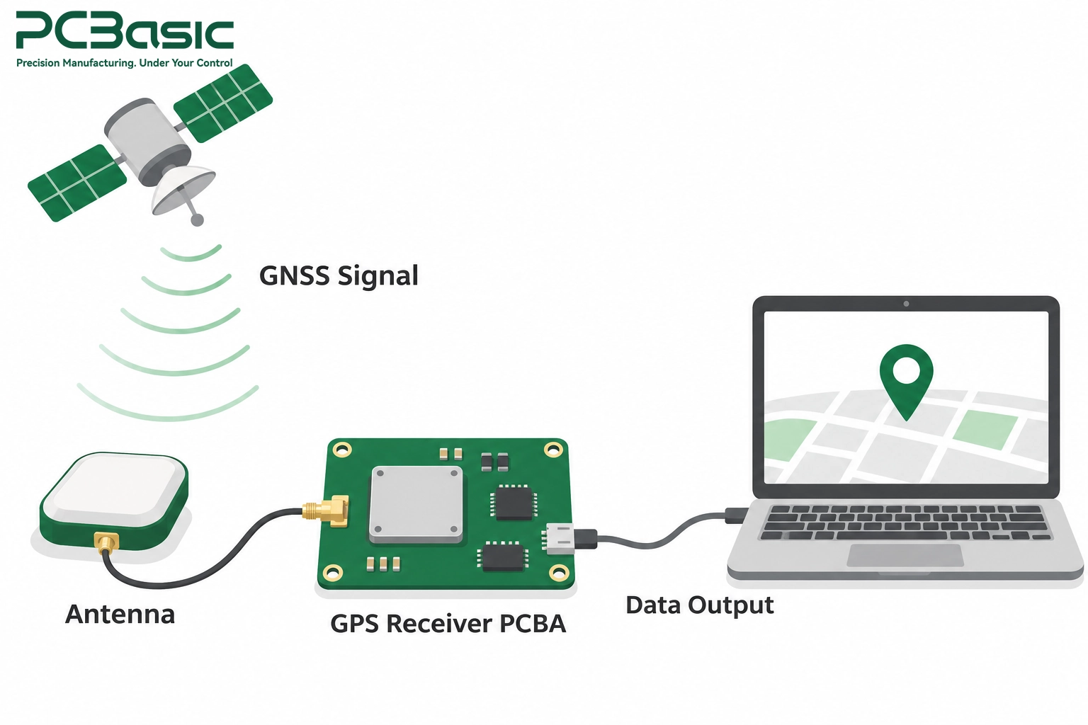
Once physical checks pass, power up the GNSS
receiver PCB assembly and interface with its supported UART, SPI, or I2C port
using the appropriate adapter and software. Effective GPS receiver testing relies
on understanding what the module reports across different message layers.
Distinguishing
Serial Communication from Fix Status
• Serial Communication: Receiving boot text or NMEA strings confirms that your baud rate,
logic levels, and UART physical connections are operational. It does not prove
that the RF front-end is working.
• Satellite Visibility
($GPGSV): This sentence lists satellites in view
along with their reported signal-strength values, commonly expressed as
carrier-to-noise density ratio (C/N₀), when available. Note: A satellite listed
in GSV is reported as being in view, but it is not necessarily tracked or being
used in the current position solution.
• Position Fix ($GPRMC /
$GPGGA): The status flag in $GPRMC (A for valid
data vs. V for invalid data) indicates whether the reported navigation data is
valid, but does not by itself confirm a 3D position.
Confirm the
required fix type using GSA or the receiver’s proprietary navigation-status
message. NMEA talker IDs vary with constellation settings, so the receiver may
output $GNRMC rather than $GPRMC.
Evaluating
Signal Levels
When evaluating $GPGSV output under a clear sky
or with a GNSS simulator, inspect the reported C/N₀ values. While exact expected C/N₀
thresholds in dB-Hz depend heavily on your specific test antenna, simulator
attenuation, and line-of-sight conditions, look for repeatable signal levels
under the same test conditions rather than relying on generic pass ranges. If
satellites appear with minimal signal strength or drop out instantly,
investigate your RF path.
Troubleshooting Sequence: Why a GPS Receiver
Responds but Cannot Get a Fix
When a GPS module integration yields a board
that communicates over serial but fails to acquire a fix, follow a structured
troubleshooting sequence to isolate the failure.
Step
1: Establish a Baseline with a Known-Good Board
Before debugging your test board, insert a known-good
board with the same firmware and configuration into the exact same test fixture and
environment.
• If both boards fail to get
a fix: The issue may involve shared test
conditions—check your test setup, RF cables, simulator settings, or signal
blockage.
• If only the test board
fails: The issue is more likely related to the unit
under test or its fixture contact.
Step
2: Verify the RF Path One Item at a Time
When swapping out suspect RF components (such
as a test cable or antenna), change one item at a time.
• Swap the test cable first. If
the board still fails, revert the cable and swap the antenna.
• Changing only one variable at
a time ensures you isolate whether the fault lies in a damaged U.FL connector,
a cold solder joint on the matching network, or the antenna itself.

Step
3: Inspect Local Oscillators and Component Placement
If the RF path and connections are verified,
examine internal hardware factors:
• Reference Frequency /
TCXO: Check if the Temperature Compensated Crystal
Oscillator (TCXO) or crystal has suffered mechanical or thermal damage during
reflow.
• Local EMI and Layout: High-speed digital lines or switching power-supply circuits placed
too close to the GNSS RF section can couple harmonic noise into the 1.575 GHz
band. Review ground stitching vias and shielding cans as additional
interference-control measures.
Production Testing: Signal Conditions and
Pass/Fail Criteria
For manufacturing lines scaling up volume,
manual testing is impractical. Designing an automated test fixture for a GPS
receiver PCB assembly requires defining clear pass/fail criteria and
establishing a controlled RF environment.
Test
Setup and Signal Entry
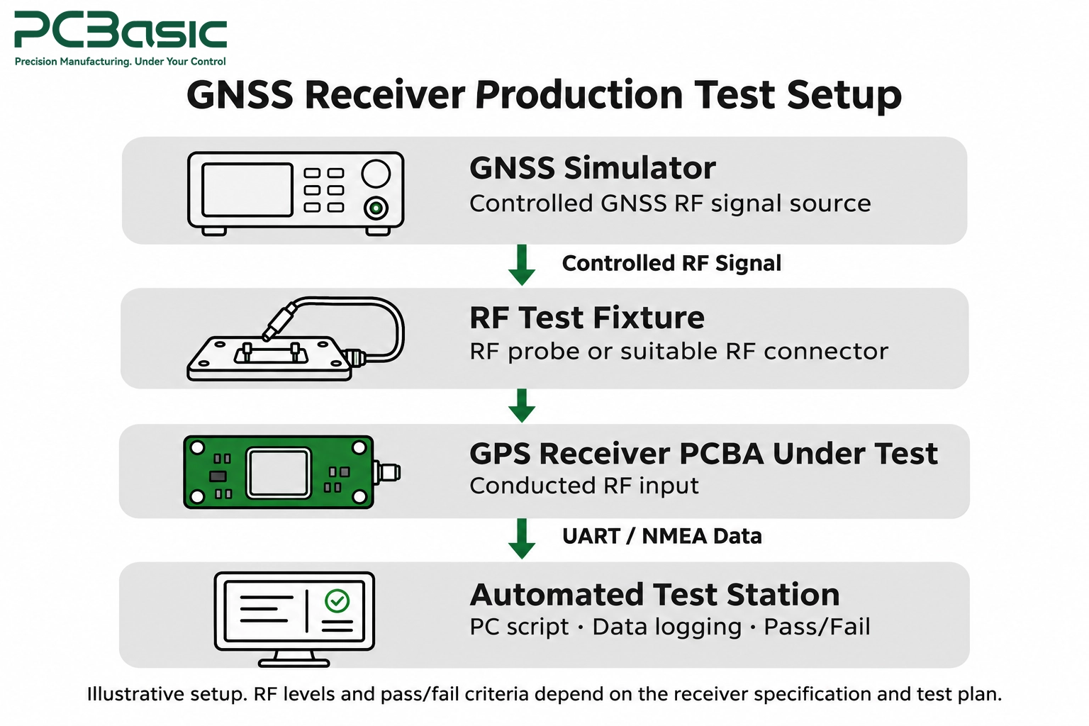
Because factories are typically indoors with
high signal attenuation, ambient satellite signals are often unreliable. Use a
conducted setup where a GNSS simulator injects a calibrated signal directly
into the board's RF input via a suitable connector or RF test probe, or use a
shielded enclosure with a controlled radiated GNSS signal. Ensure your test
plan explicitly notes whether testing occurs via a direct conducted RF port or
through the product's assembled antenna.
Defining
Production Pass Criteria
Align your automated test script with your
specific product test plan and chipset datasheet parameters:
• Handshake Time: Does the GPS receiver board acknowledge polling commands within the
expected boot window?
• Firmware / ID
Verification: Does the module return the correct
software version and hardware ID?
• Signal Acquisition and
Timeout: Under your defined simulator signal
profile, does the unit achieve a valid fix ($GPRMC status A, with the required
fix type confirmed separately) and report the required minimum number of
satellites used in the solution within your specified timeout window (depending
on the defined startup state and test conditions)?
• Current Consumption: Does the operating current match the specified current-consumption
limits, helping flag possible electrical faults such as shorts or defective
components?

Conclusion
Validating a GPS receiver PCB assembly demands
meticulous attention to detail across every stage of manufacturing. From
verifying the GPS antenna connection during physical inspection to structuring
logical troubleshooting flows and defining clear production pass criteria, a
methodical approach ensures high reliability.
Partnering with PCBasic for your next build? Share your receiver model, antenna configuration, and
specific acceptance requirements so our engineering team can tailor your SMT process
and test fixtures to your production requirements.
FAQs
Q1: Why does my GPS receiver work outdoors but
fail completely inside a factory?
GPS satellite signals operate at extremely low
power levels at the Earth's surface and can be significantly attenuated by
standard building materials like concrete, steel reinforcement, and some types
of coated glass. For repeatable indoor testing on a production line, you should
use a controlled conducted or radiated GNSS test system.
Q2: Does a slow Time to First Fix (TTFF) always
mean the backup battery is dead?
Not necessarily. While a dead backup battery or
unpowered backup supply pin can cause a cold start (through loss of retained
time and navigation data, depending on the receiver), a slow TTFF can also be
caused by poor antenna placement, weak signal injection in a test fixture, or
missing assistance data when the test relies on assisted GNSS (A-GNSS).
Q3: Can a missing NMEA output be diagnosed
purely as a crystal oscillator failure?
No. While a damaged reference oscillator can
prevent normal receiver operation, missing NMEA output is frequently caused by
simpler issues, such as a baud rate mismatch in the terminal software, an
unpowered module due to a bad LDO, or an incorrectly configured interface or
boot-mode pin.
Q4: How can I mitigate high-frequency switching
noise affecting my GPS receiver board?
Ensure your DC-DC switching regulators do not
introduce significant harmonics or broadband noise into the GPS L1 band (1.575
GHz), or use linear regulators (LDOs) with suitable output-noise and Power
Supply Rejection Ratio (PSRR) performance at the relevant frequencies dedicated
to the GNSS supply pins. Place the recommended ceramic decoupling capacitors
directly adjacent to the power pins and keep digital traces away from the RF
input.